DTS Technology Overview
Today the use of optical fiber as Distributed Temperature Sensor (DTS) provides the most powerful way to measure temperature distribution over several tens of kilometers with a meter scale spatial resolution. In this way, many electronics sensors (Thermocouples, RTD…) can be replaced by installing a standard Multi mode or Single mode fiber optic cable along the structure to be monitored providing an electrically insulated, electromagnetic interference insensitive and cost effective solution.
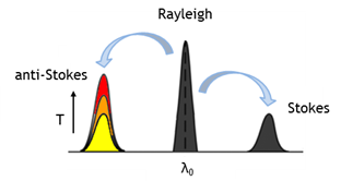
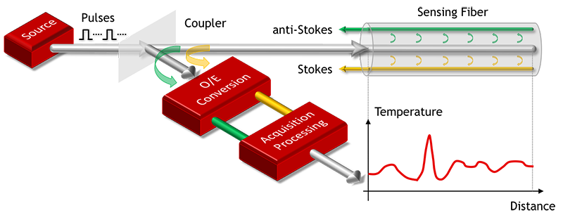
The key physical mechanism which is exploited to effectively infer the temperature of the fiber (and of surrounding environment) through light wave measurements is the so-called Raman effect, an optical scattering phenomenon discovered in liquids in 1922 by C.V. Raman, and involving the generation of new light spectral components in presence of a strong light propagating through a gas, liquid or solid. The Raman effect is an inelastic scattering between light (photons) and molecular vibrations (phonons) of the silica glass, hence involving a decrease (or increase) of photon energy (i.e. optical frequency) after the photon-phonon interaction. In particular, two spectral components so called Stokes and anti-Stokes, symmetrically frequency shifted with respect to the incoming light are generated. In Optical Fiber (Silica glass) their intensity will be maximum at a given frequency shift value, known as the Raman frequency shift ≈ 13.2 THz.
 While the intensity of the anti-Stokes light exhibits a strong dependence on the temperature, the intensity of the Stokes light is found to be only slightly temperature dependent. Stokes and Anti-Stokes light are the key components for the Distributed Temperature Sensors and in order to provide a robust temperature measurement, usually the power ratio of the anti-Stokes over the Stokes light is used.

where PS and λS are the power and wavelength of the Stokes light, PAS and λAS are the power and wavelength of the anti-Stokes light, h is the Planck’s constant, Δν is the Raman frequency shift, and kB is the Boltzmann constant.
In order to obtain the spatial information in RDTS systems, optical time domain reflectometry (OTDR) techniques are usually exploited. This method consists in launching short laser pulses into the sensing fiber and detecting the backscattered spontaneous Raman signal with high temporal resolution. The spatial resolution, (i.e. the minimum distance that the system can resolve) is related to the pulse width, for example, 10 ns pulse width correspond to 1 m spatial resolution.

There are two different fiber configuration adopted by Raman DTS systems: Single-end scheme and Loop scheme.

In a Single-end fiber configuration only one end of the fiber is connected to the DTS control unit, pulses are sent in forward direction only, while in a Loop fiber configuration both fiber ends are connected to the DTS control unit, and pulses are alternately sent in forward and backward directions.Although the single end fiber configuration is adopted in wide range of applications, it requires the proper characterization of the differential Stokes anti-Stokes attenuation as a function of distance during the step of system calibration. Moreover, there are particular applications where the differential attenuation are not constant in time due to the ageing process (tens of years) or external harsh environmental conditions (e.g. high acidity, ionizing radiations), hence requiring a periodic system re-calibration. On the other hand, the loop fiber configuration provides a smart and effective solution to intrinsically compensate differential attenuation making the loop scheme suitable also for harsh environments and/or environments where periodical system calibrations are not possible.


